<lasermtv07/> home
Making a CPU from scratch
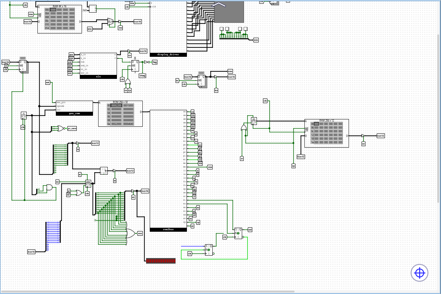
2026-02-07CPUS are kind cool, aren't they? I mean, they give us programmers employment (well, some of us). Hence, I wanted to know how they work, and to find that, I designed a simple CPU. I'm gonna be simulating it in a program called Logisim evolution, though I might make a hardware build one day, too.
Parameters
My CPU has a 16bit word size (meaning it can work with unsigned values from 0 to 65 535 or signed values -32 768 to 32 767). The adress space has 12bits, meaning that the computer can store 4096 words or 8192 bytes.
It also has 3 registers - A,B and X. The first two are directly connected to the ALU, which supports addition, subtraction and bitwise logic operations. To perform a computation, the parameters are loaded into A and B, the operation is performed and the result is stored into A
The X register is the index register. It's used by indexed instructions and it shifts the value outputted to the adress bus by its content (for instance, if the register value is 5 and LDAX 12 is called, it loads the contents of address 12+5=17 into A). Indexed variants of instructions are denoted by ..,x.
The ISA
The ISA available on the GitHub page shows instructions as they're understood in assembly, which combines several instruction variants into one instruction.
Here is the full ISA, with all instruction variants kept separate and with binary opcodes:
0 0001 LDA $mem - load data from memory to A
0 0010 LDB $mem - load data from mem to B
0 0011 STA $mem - store data from A to memory
0 0100 STB $mem - store data from B to memory
0 0101 ADD - load $mem into B, add A to B, store to A
0 0110 SUB - load $mem into B, subtract B from A, store to A
0 0111 AND - load $mem into B, bitwise and from A to B, store to A
0 1000 OR  - load $mem into B, bitwise or from A to B, store to A
0 1001 XOR - load $mem into B, bitwise xor from A to B, store to A
0 1010 JMP $mem - jump to memory address
0 1011 JPZ $mem - jump to memory address $mem flag is 0
0 1100 CALL $mem - call a subroutine
0 1101 RET - return
0 1110 JNZ $mem - jump to $mem if the reult of last op was not 0
0 1111 EXT

1 0001 LDAI - loads the next word into A
1 0010 LDBI - loads the next word into B
1 0011 LDAX $mem - loads $mem+X into A
1 0100 LDBX $mem - loads $mem+X into B
1 0101 ADDI $mem - loads $mem into B, adds and stores to $mem
1 0110 SUBI $mem - loads $mem into B, subs and stores to $mem
1 0111 INX - increments X
1 1000 DEX - decrements X
1 1001 LDX $mem - load $mem into X
1 1010 LDXI - load next word into X
1 1011 JNX $mem - jump to $mem if x!=0
1 1100 STAX $mem - store contents of A to $mem+x
1 1101 STBX $mem - jump when x is nonzero
1 1110 CMP $mem - loads $mem into b, compares
1 1111 STX $mem - stores index register to m
The extension bit and parameters
The ISA is designed to contain the instruction and its memory parameter in one word, as following:
0001 000000000001
with red representing the opcode and green the parameter.
This is a remnant from an older design of the CPU that in hindsight isn't ideal, but oh well.
But you might've noticed that the opcodes in the ISA consist of 5 bits. That is because the first bit is the extension bit and it's actually a CPU flag set by the EXT instruction.
The second part of the ISA, the one with that one bit set to 1 is called the extended part of the ISA. The flag is toggled off after the extended instruction is performed, so, for example, the LDAI instructions will be written as f000 1000 in memory.
Conditionals
For the CPU to be Turing complete, it needs conditional branching. That is achieved with the zero flag next to the ALU. This flag is set after each ALU operations if the result of that operation is 0. Apart from the classic ALU operations, it can also be set
with the CMP instruction, which loads the word located at $mem into B and performs the subtract operation without modifying the registers, setting the zero flag and performing a simple comparison.
Input and output
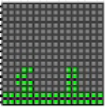
The CPU uses memory mapped IO, mapping a 16x16 display onto the adresses ff0-fff and mapping four buttons on fef.
These buttons are mapped in this pattern:
0000 0000 0000 0000
with red correponding to button 1, green to button 2 etc. For example, if only button 1 is pressed, the value will look like this:
1111 0000 0000 0000
Assembly and programs
The repo contains a simple assembler, its documentation and a few example projects. Most of them are pretty self explanatory, except maybe test.asm, which contains a simple game I programmed:
Conclusion
This was an interesting project and taught me a lot, though I'm not satisfied with some of the decisions I made. I'd still love to try something similar again, though. The project is available on GitHub and I also made a video about this, so you can check that out.
Screenshot
(c) lasermtv07, 2026